

This page is a record of my experiences while rebuilding the small-block Ford V8 engine in my 1968 'J-code' Mustang fastback.
This page also containts some additional information related to the 1968 small-block V8 engines fitted to the Mustang, specifically the 302ci 'J-code' engine, C8OE-F cylinder heads and elusive 1969 302ci C9OE-E cylinder heads.
I hope you find this page useful... * NEWLY UPDATED - 21/10/2015 *
- Matt
Part 1 - Removing the hefty iron V8 lump
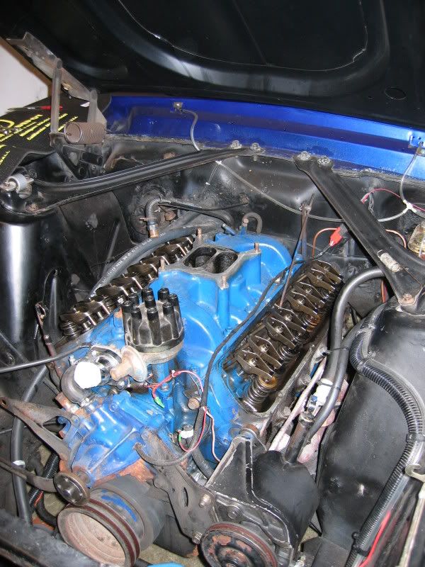
My 1968 Fastback was optioned from the factory with the 302ci V8 with 4V (four venturi or four barrel) carburettor, rated 230hp@4800rpm and 310lb/ft@2800rpm of torque in stock trim. Unfortunately, I already knew that the engine installed within my '68 Mustang had been modified by previous owners, with many of the factory parts MIA.
From simply looking at the car a well informed person could probably tell that it had been drag raced in the past. With extended leaf spring shackles (to aid weight transfer), aftermarket 'SHELBY' lettered aluminium 4-barrel intake, long-tube headers and with the engine running it had more of a lopey idle. All of this hinted at some 1/4 mile action, which also usually means possible extra wear and abuse.
 |
 |
 |
 |
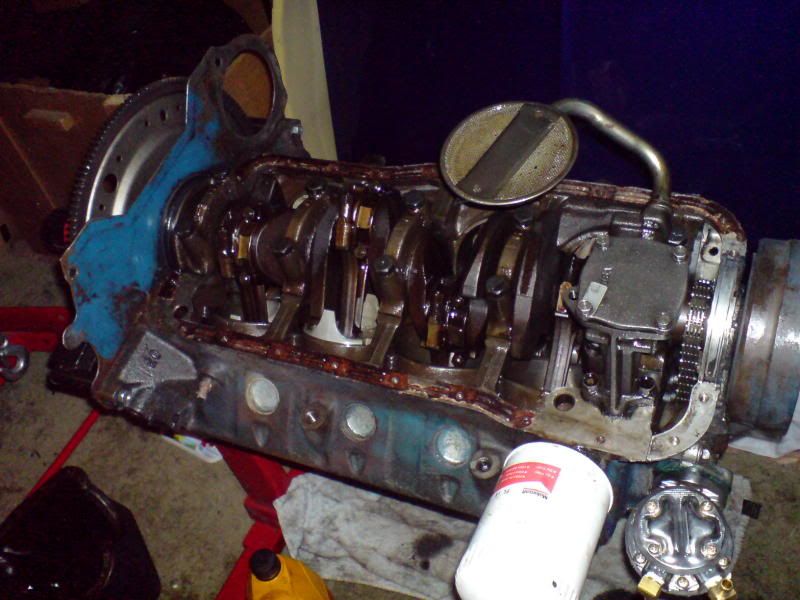
With oil-leaks, poor starting and a niggling feeling that all wasn't well with the aging V8, I chose to strip the engine down for further investigation while performing other restoration work on the engine-bay.
The first few steps were to drain the engine of fluids, remove the carburettor, disconnect all electrics, pull the headers etc. At this point I chose to remove the valve covers and take a quick peek inside. Knowing that the engine had been played with by previous owners, I looked quickly at the cylinder head casting numbers. I could see a big '302' cast into the top and a big 'E' at the other end. I thought nothing of it and continued with the engine removal, at least it was a 302 as per the VIN and not a 289.
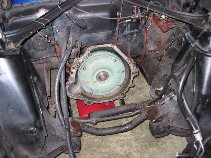
I chose to leave the C4 automatic transmission in place at this point. The photos above already show evidence of leaking valve covers, header gaskets, inlet manifold and front valley gasket. Generally a good coating of oil all over!
Part 2 - Teardown & fact finding
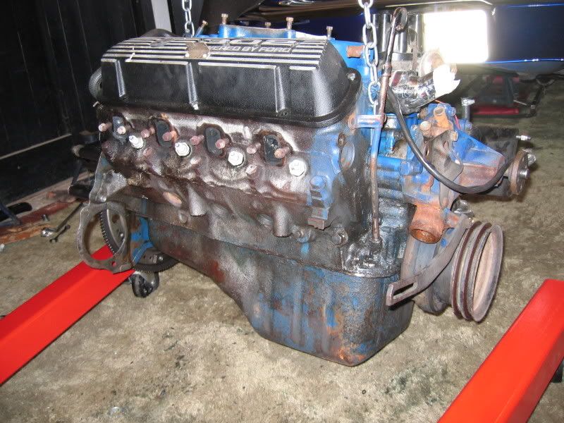
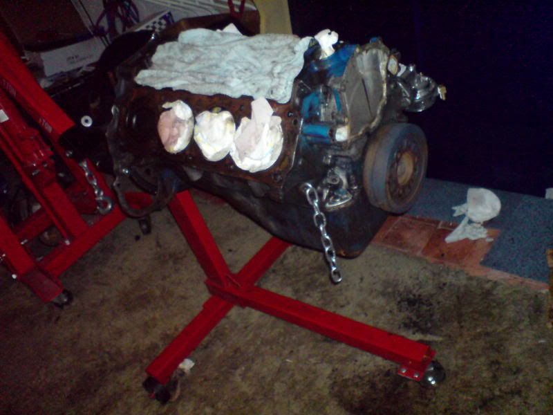
Once the engine was safely on a stand, I continued to tear it down piece by piece inspecting each part as I went.
The distributor was removed first, only to be greeted by the all to familiar clank of the oil-pump driveshaft falling into the oil pan. Obviously the retaining washer had not been fitted, or had come adrift. No turning back now, the oil-pan has to come off!
Cylinder head inspection
I removed each rocker arm, fulcrum and pushrod, bagging and labelling as I went to be sure I could return them to their original position if necessary. It was at this point I noticed that the narrow tips on some of the exhaust valve stems, while some had little caps, others had rings, some had nothing. Confused by these odd differences I started to look a little deeper, noting the casting numbers down. Having previously noted that my 1968 Mustang had a 'J' in the VIN, which denotes the 302ci V8 with 4V carburettor and C4 automatic tranmission, I knew the casting numbers should be C8OE-F and have '4V' cast into the top of the head. I didn't see '4V' I saw 'E' and a date-code number of 8M16 next to it, but I also noticed the Cleveland foundry casting mark on the top surface of the heads.
The fact-finding continued as the heads were removed from the block. I then flipped them over and looked closely at the casting numbers underneath. It immediately became clear that one of the previous owners had swapped-out the cylinder heads as the casting numbers read C9OE and not C8OE as expected. The key component of the 1968 'J-code' engine is the cylinder heads and these vital parts were MIA. Frustrated to learn that the 'J-code' engine in my car wasn't as it left the factory, I would later find out that this was probably a small blessing in disguise. I do recall feeling rather annoyed about it at the time!
After picking myself back-up I did some further research into the C9OE-E casting numbers, but I could not find them listed in any of the casting number references I had. I knew they were obviously 1969 (or later) parts because of the casting number itself...
| Cylinder Heads - Casting Number Decode | ||
|---|---|---|
| C | Decade | 1960s |
| 9 | Year of decade | 9th year = 1969 |
| O | Model design | Fairlane(all) and Torino 1967-1976 |
| E | Engineering component | Engine |
I also knew these parts were from a 1969 application because the date code cast into the cylinder heads was 8M16 (16th of December 1968). Unusually for 1969 parts, the C9OE-E heads had an adjustable valvetrain with press-in 3/8" un-shouldered rocker studs. These specific parts combined with the date-code of the cylinder head castings reflected a "pre-L4" revision status, confirming them as early 1969 parts.
After a few hours of internet searches and reading many (often conflicting) references, I learned that the C9OE-E heads were a 1969 specific part with a closed 58.2cc combustion chamber design. As part of my reasearch I also confirmed that these heads used longer-stem valves with narrow-tip exhaust valves for use with wear caps and the fully adjustable valvetrain. Details of these specific heads may not be found in many of the published casting number references (except Beb Mannels aforementioned book apparently).
After my initial frustrations, I realised the slightly larger chambers of the C9OE-E heads would offer a lower 9.5:1 CR (compression ratio) when compared to the 10:1 CR of C8OE-F heads with their small 53.5cc chambers. So although the C9OE-E heads are "incorrect" for a 'j-code' engine, the slightly lower compression ratio would likely work better with the modern poorer quality unleaded fuels.
Continuing with what I had in-front of me, it turned out to be very fortunate that I chose to look deeper at the engine, because here's what I found...
 |
 |
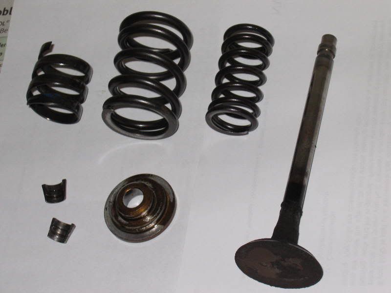
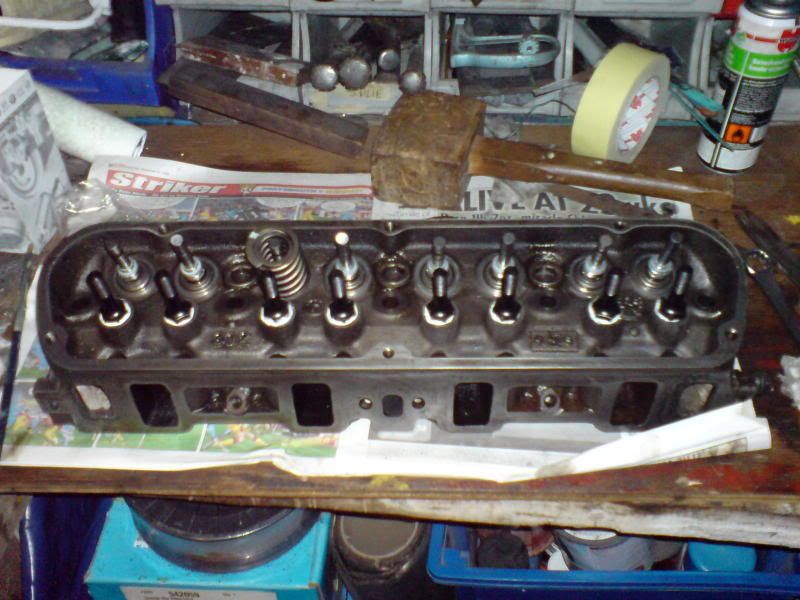
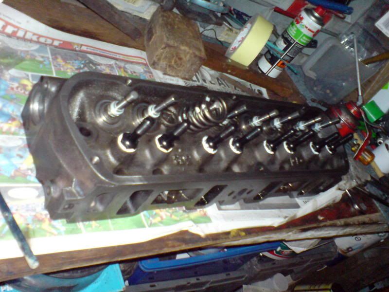
The LH image shows the long-stem valves (with reduced tip diameters on the exhaust valves for use with wear caps), double valve-springs with dampers and aluminium spring retainers. The exhaust valve (shown) should have a small wear cap which fits over the tip to bring the valve-tip back to the correct diameter. These were either worn badly (some were worn right through) or missing entirely. I later found some reminents of these in the oil-pan, fortunately they were too big to enter the oil-pump where they would have done a lot of damage.
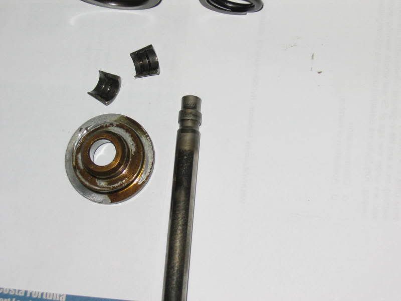
The second (RH) photo shows how the high-tension valve springs had cut into the lightweight aluminium retainers. Logically installing high-tension valve springs with lightweight aluminium retainers may offer increased horsepower, ideal for a drap-strip warrior, but not for a road going car. In my opinion avoiding the potential for wear and increasing longevity is a good reason not to run race-only specification parts on the street!
Race engines require much more attention and require regular tear-down and inspection to keep them in tip-top condition. Obviously the previous owner, bought the race-spec parts but didn't stop think of the consequences of the changes they made. High-tension steel valve springs being held in-place by soft aluminium retainers was bound to give wear problems over a period of time. Hindsight, is a wonderful thing and something I fortunately can learn from without having made the fatal decision in the first place!
Another problem was that the valve seats on both cylinder heads showed evidence of poor valve sealing. Possibly due to incorrect valve-lash adjustment with the hydraulic (flat tappet) camshaft. With the valve seats being in poor condition, there would be some extra work required to bring them back to life.
 |
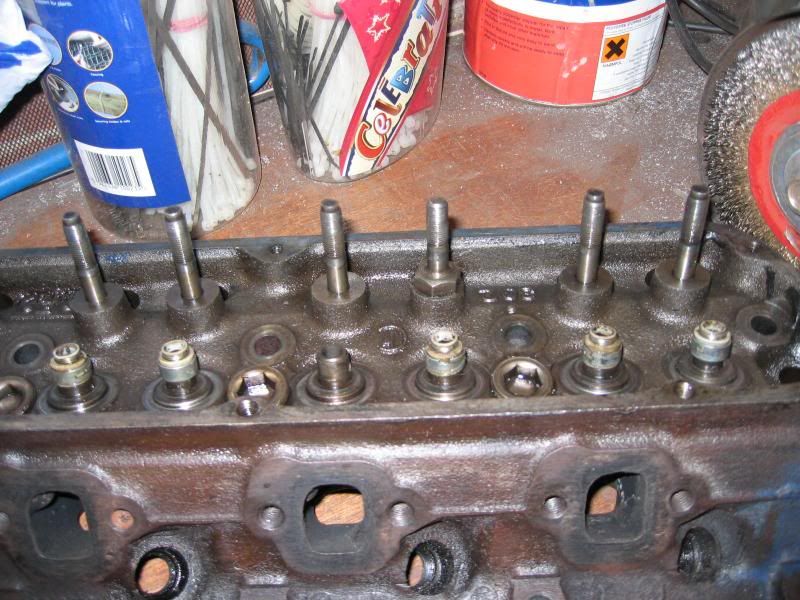 |
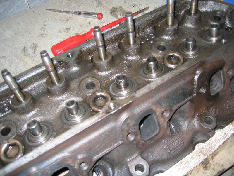
Another item I noticed were the valve stem seals; they were also non-stock. Obviously the valve guides had been machined down to accept the dual valve-springs and modified viton or teflon seals. The images below show how guides have been milled down (poorly) and the aftermarket valve stem seals. Note also shows the stock type press-in rocker arm studs, except for one which has obviuosly failed in the past and been replaced with a screw-in replacement.
Most people at this point would swap-out the old, heavy, cast-iron cylinder heads at this point and go with some fantastics new aluminium versions. But unfortunately as costs had already started to mount up with other things I wanted to change or update, I chose to keep the original cylinder heads and invest some time and effort into them instead of looking for replacements.
Inspecting the bottom end
I chose to only partially strip the bottom end of the engine, removing the oil pan, balancer, water-pump & timing cover for inspection. Other than debris in the oil-pan, there were no signs of damage or evidence of excessive wear so I left well alone. If it ain't broke, don't fix it!
However, the pistons (once cleaned) revealed a +0.030" overbore, making the true engine capacity 306ci (4.030" bore, 3.00" stroke).
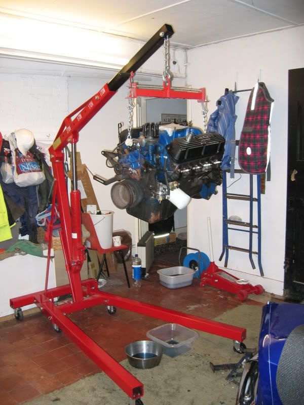
Note the 3-wheel engine stand in the images below, I'd highly recommend spending a little extra an getting the far more safe and stable 4-wheel version. Moving a heavy iron V8 around on one of these is not funny!
 |
 |
With the timing cover removed, it was apparent that stock timing chain had stretched, probably under load from the high-tension double valve-springs. I'd planned to replace this anyway as I had already decided to fit a new, milder camshaft.
Other items
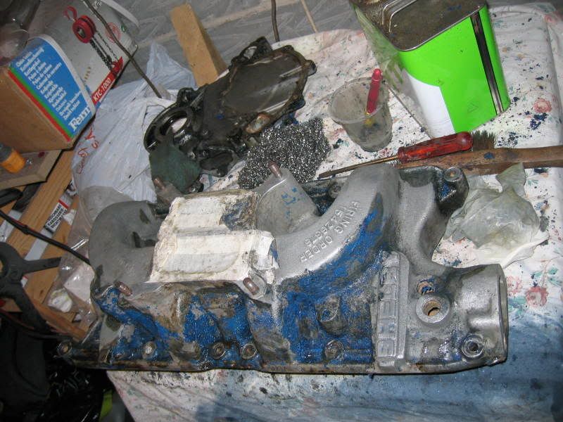
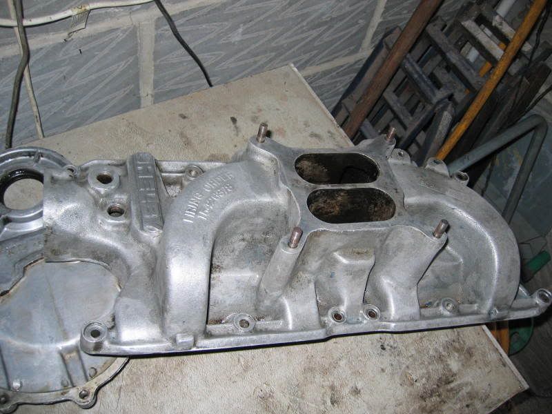
Keeping inline with my ethos of refurbish, not replace I cleaned up the unusual and rare old 'SHELBY' lettered inlet manifold rather than replace it with a modern version. While this will likely give up a few horsepower against a modern intake design, it's a cool looking old-skool part and fully salvageable. The original timing cover was also fine and fully re-usable. Both items were cleaned by hand using copious amounts of paint stripper and elbow grease.
 |
 |
 |
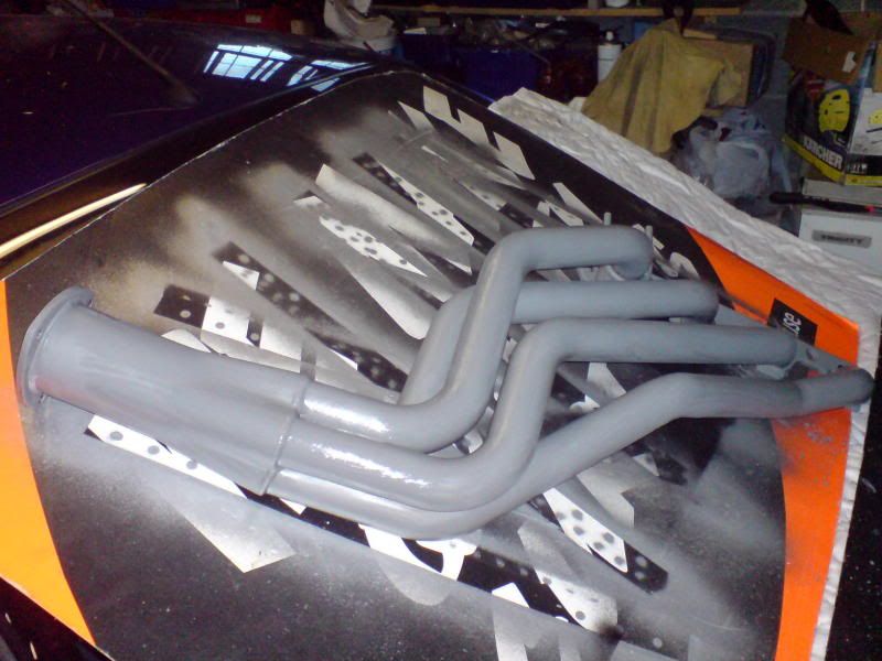 |
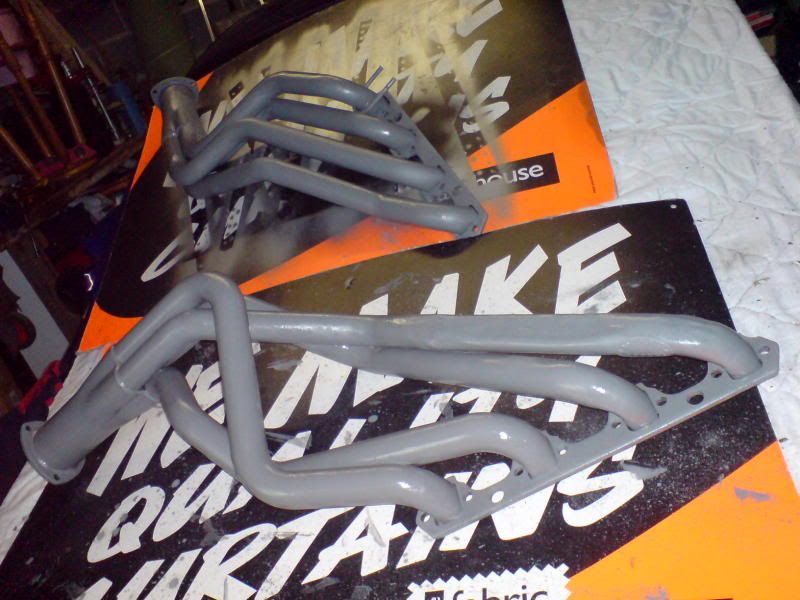
I was lucky enough to be offered a set of nearly new Hooker Super-Comp headers by local fellow Mustang owner who'd recently completed a T5 conversion on his '65 fastback (thanks Steve!). They wouldn't fit his car following the swap so were surplus to requirements, fortunately for me.
I just paint stripped cleaned and painted them with Eastwood's header paint to smarten them up - Not too shabby!
Hopefully replacing the headers with new (thicker) gaskets should address the leak at the cylinder heads.
Part 3 - Putting it back together
Keeping things on a relatively tight budget (if only to avoid the inevetable spiralling of costs caused by buying nice new shiny things!), I chose to keep the rebuild fairly stock with a few mild upgrades to aid reliability or address inherent weaknesses.
Cylinder head refurbishment
After being stripped, the heads were fully cleaned, inspected for damage and their trueness checked. Fortunately there were no cracks or other issues with the castings, except for one of the press-in rocker studs having been replaced with a screw in type and some of the press-in type having galled threads.
The high revving 289 'HiPo' V8 had several valvetrain upgrades over other small-blocks, including the addition of screw-in rocker studs. A popular upgrade is to machine the rocker stud bosses on stock cylinder heads to accept guideplates and screw-in studs replicating the 289 HiPo design. To improve reliability, I chose to remove all of the press-in style rocker studs and replace them with screw-in studs. This would alleviate the problem of trying to fit a press-in stud back into the boss which had been modified previously, plus it'd also lessen the chance of a press-in stud coming loose with higher than stock tension valve springs.
 |
 |
I removed the press-in studs (using a combination of nuts, washers and a socket as a tool to pull the studs out) and the tapped the required 7/16"-14 (UNC) thread into the cylinder heads. The threads/holes run through into the cylinder head water jackets, so I added a liberal dose of sealer when installing the new screw-in ARP rocker studs, as a little insurance against oil meeting water.
While I have ported and polished a couple of cylinder heads in the past (for Mini's and MGB's), for simplicity I chose to only clean up and de-coke the chambers and ports, removing only minor casting irrgularities and checking for misalignment between the ports/manifolds. External casting irregularities and sharp edges were removed with a die-grinder, just to make them look nicer and easier to handle.
Many people would outsource this type of work to a machine shop, but I chose to do it myself. It's amazing what you can do in your home garage, with a few basic tools and a little know how.
Installing and breaking-in a new camshaft
Installing a new camshaft, especially a flat-tappet type is not to be taken lightly. Physically installing the cam is one thing, but giving it the best start in life by following a proper break-in procedure and pre-lubing the parts is another. Spending a few extra bucks on proper assembly lube to give a flat-tappet cam the best possible chance of surviving when the engine first fires is just common sense to me. Anything you can do to ensure the cam doesn't get prematurely wiped out, will just help your wallet. Failing to use the proper lubrication may not cause you issues, but why take that chance with your hard earned cash...?
I decided to go for an original Ford cam grind (original Ford part #: C9OZ-6250-C) mainly to keep things in the correct era, after all a 1968 Mustang has to sound right. Obviously Ford don't make these parts anymore, but Speed-Pro offers a reproduction made to the original Ford specifications (Speed-Pro part #: CS108R). I added new corresponding anti-pump up lifters/followers, new pushrods, cam & crank sprokets and new timing chain to keep everything in sync. Everything went together perfectly, with new seals and gaskets the original timing cover was bolted back into place with a new chrome dipstick tube and refurbished timing pointer.
A new standard volume oil pump was stripped, checked, clearanced and reassembled before fitting with the fully cleaned original oil pickup and strainer. A new Ford Racing hardend oil-pump driveshaft was also added, prior to refitting the stock cleaned and repainted oil pan.
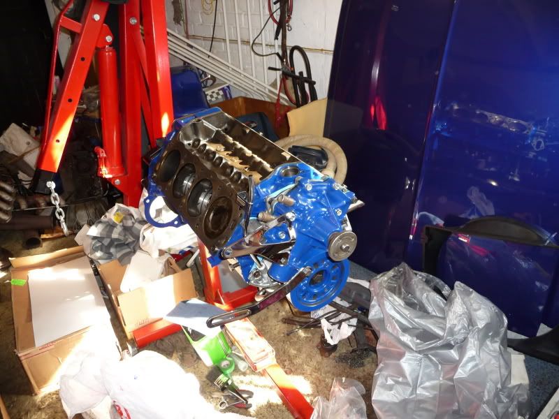 |
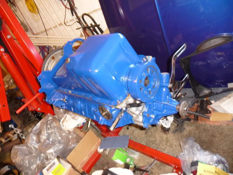 |
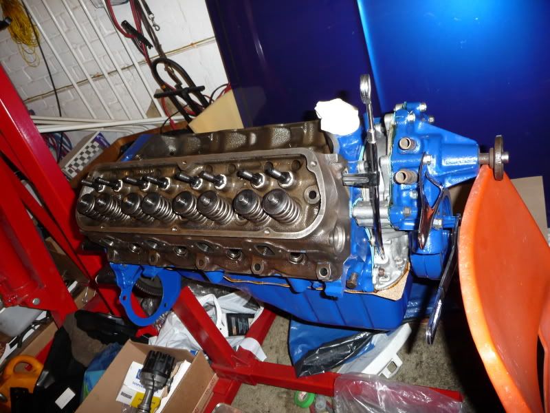 |
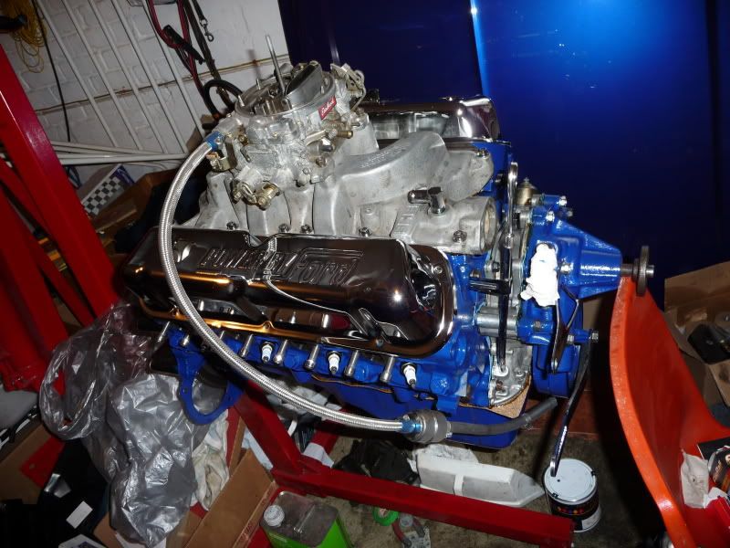 |
The images above show various stages of the final assembly process, with all new gaskets & seals. I think it looks rather good, especially with the chromed OE style "powered by Ford" valve covers.
The original single-point Autolite distributor was fully checked for play and wear, showing only light wear it was fine to be re-used. However, before reinstalling, I chose to swap-out the old contact breaker points for electronic ignition.
All back together and ready for the first fire-up and cam break-in.
Annexe A - Detailed specification & Part numbers
| Cylinder Head | |
|---|---|
| - Cylinder Head Material | Cast Iron |
| - Castings | Ford 1969 "C9OE-F" Casting |
| - Combustion Chamber Capacity | 58.2cc (9.5:1 CR) |
| - Inlet Valve Specification | Manufacturer = Melling Part # = V1137 (Summit) Material = Steel Collets = Single collet groove, 45-degree Head Dia. = 1.781" Length = 5.050" Stem Dia. = 0.342" (11/32") |
| - Exhaust Valve Specification | Manufacturer = Melling Part # = V1135 (Summit) Material = Steel Collets = Single collet groove, 45-degree Head Dia. = 1.452" Length = 5.068" Stem Dia. = 0.3418" (11/32") |
| - Valve Springs | Manufacturer = Speed-Pro Part # = VS270 Specification: - 84-94 lbs @ 1.77" closed - 225-241 lbs @ 1.38" open - 1.2600" coil bind - 1.70" installed height |
| - Retainers | Manufacturer = Speed-Pro Part # = VK115 Type = One piece (for use with VS270 springs). |
| - Locks / Collets | Manufacturer = Speed-Pro Part # = VL200 Type = Single Groove, 45 deg. |
| - Valve Guides & Stem Seals | Material = Ductile iron - Machined to 0.0500" Teflon valve stem seals - Manufacturer = Crane Cams - Part # = 99826-16 |
| - Rocker Arm Studs | Screw-in, non-guideplate type Manufacturer = ARP Part # = 134-7101 Head = 3/8"-24tpi (UNF) Base = 7/16"-14tpi (UNC) Installed Height = 1.75" |
| Camshaft & Valvetrain | |
| - Camshaft | Type = Hydraulic, flat tappet Ford Specification = C9OZ-6250-C Manufacturer = Speed-Pro Part # = CS108R Specification: - Inlet, Advertised Duration: 298 deg. (218 deg. at 0.05") - Exhaust, Advertised Duration: 298 deg. (218 deg. at 0.05") - Inlet, valve lift: 0.460" - Exhaust, valve lift: 0.460" - LSA: 113 deg. - Firing order: 1-5-4-2-6-3-7-8 (289/302) - Useful Link |
| - Pushrods | Steel (non-hardend) |
| - Rocker Arms | Cast, self-aligning "rail" type |
| Fuel & Air Delivery | |
| - Carburetor | Manufacturer = Edelbrock Part # = 1405 Specification: - Performer Series, 600cfm - 4x Venturi (4V), vacuum secondaries - Manual Choke |
| - Fuel Pump | Type = Mechanical Manufacturer = Carter |
| - Inlet Manifold | Type = 4-barrel, dual-plane, Aluminium Manufacturer = Ford |
Annexe B - A little history and background information
For the 1968 mode year, Ford made some significant changes to the small-block V8 engines offered in the Mustang. The capacity of the small-block V8 was increased from 289 cubic inches (4.7 litres) to 302 cubic inches (5.0 litres) accross the board. This increased capacity also meant an increase in horsepower and torque on all normal production engines.
Following the sucessful introduction of the 'High Performance' 390ci (6.4 litre) FE series Big-Block V8 in 1967, Ford chose to drop the solid-lifter 289 4V 'HiPo' from production at the end of 1967. This only left the customer the choice of two hydraulic-lifter small-block V8 engine variants the 2V and 4V carburettor versions.
Three small-block V8 engines were installed into Mustangs at the factory, these were the 289 2V 'C-code', 302 2V 'F-code' and 302 4V 'J-code'. Earlier 1968 2V carburettor models recieved the 289 2V 'C-code' engines (possibly due to a large stock of these engines), but these were later superseded in production by the 302 2V 'F-code'. All 4V carburettor small-block cars for 1968 recieved the 302ci 4V 'J-code' engine, which is what my Dearborn built 1968 fastback recieved.
There's little that distinguishes the J-code from its bretheren, obviously the 4 barrel carburettor and corresponding cast-iron inlet manifold, but the key unique components of the J-code V8 are the C8OE-F cylinder heads. It's these high-compression cylinder heads with their small 53.5cc combustion chambers that allowed this little mill to produce a mild mannered 230 horsepower with just over 300 lb/ft of torque. However, compared to the earlier 289 'HiPo', the 302 'J-code' engine was little more than a standard production engine with higher compression.
Cylinder head and valvetrain evolution
The 260ci and early 289ci small-block V8 engines used an adjustable "pushrod guided" valvetrain. These engines had narrow, close-tolerance pushrod holes cast into the cylinder heads which were designed to "guide" the pushrods in order keep the rocker arms correctly aligned on the valve tip. Producing these close-tolderance pushrod holes required accurate cylinder head machining (read expensive) and mandated the use of more expensive hardend steel pushrods to avoid excessive wear on the side of the pushrod.
In mid 1966 Ford introduced a revised valvetrain which had adjustable "valve-stem guided" rockers. This meant the cylinder heads no longer needed close tolerance machining as per the "pushrod guided" design, so these later heads have a larger (unguided) pushrod hole. These engines also recieved unhardend pushrods (as the pushrods no longer needed tolderate side-loading to keep the rockers in alignment) and a corresponding updated rocker arm with cast-in "rails". These engineering changes probably made production much simpler and cheaper, as they did little for performance (it's worth noting that the "HiPo" 289 retained the "pushrod-guided" valvetrain throughout production).
Early (pre-L4) 302ci engines recieved the same adjustable valvetrain as the late 1966 and 1967 289ci engines, with straight 3/8" UNF press-in rocker studs. Beginning in mid-1968 however, non-adjustable (shouldered 5/16" UNF) positive-stop rocker arm studs were installed along with two-peice spring retainers. These same engineering changes included the use of longer valve stems, adding exahust valve-tip wear caps and different (longer) pushrods. This later valvetrain configuration is what many people refer to as the "post L4" configuration. I believe that Ford made these changes in order to try and combat rapid valve (tip) wear caused by the "rail" type rocker arms.
For more information about other variants I highly recommend Tom Monroe's book "How to Rebuild Small-Block Ford Engines" along with Bob Mannel's book "Mustang and Ford small block V8 1962-1969". However, one of the very best references I've found is the (free) NPD parts catalogue!
Annexe C - Factory specifications
Some useful details about the 1968 302ci 4V 'J-code' engine...
| Short Block Specification | |
|---|---|
| Block Marteral | Cast Iron |
| Configuration | 90-degree Vee |
| Capacity | 302 cubic inches (5000cc) |
| Bore | 4.00 inches (101.6mm) |
| Stroke | 3.00 inches (76.2mm) |
| Piston Specification | Cast |
| Connecting Rod length | 5.090 inches |
| Camshaft Type | Hydraulic flat-tappet |
| Cylinder Head Specification | |
|---|---|
| Cylinder Head Material | Cast Iron |
| Casting Number | C8OE-F |
| Combustion Chamber Capacity | 53.5cc (10:1 CR) |
| Inlet Valve Size | 1.78 inches |
| Exhaust Valve Size | 1.45 inches |
| Valve Guide Material | Ductile iron |
| Rocker Studs | Press-in, 3/8" UNF thread |
| Pushrods | Steel (non-hardend) |
| Rockers | Cast, self-aligning "rail" type |
| Rocker Ratio | 1.6:1 |
| Other Specifications | |
|---|---|
| Carburettor Type | Autolite |
| Type / Venturi / Choke | Downdraft, 4-Venturi with auto-choke |
| Inlet Manifold Type / Material | 4V, low-rise Cast Iron |
| Exhaust Manifold Type / Material | Conventional Cast Iron |
| Ignition System | Conventional single-point distributor with vacuum advance |
| Oiling System | Conventional, wet-sump (gear driven by the camshaft via a drafshaft connected to the distributor) |
Annexe D - Final transformation
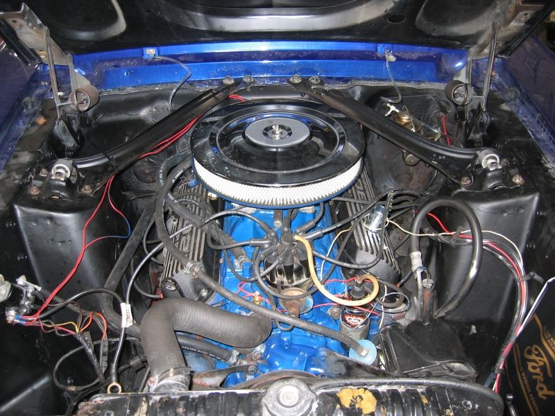
BEFORE
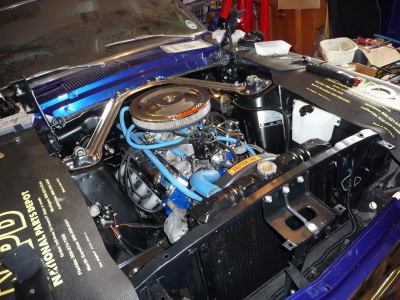
and AFTER...

There's no better satisfaction than seeing and driving a car you've restored that's powered by an engine you built.